| |
Profile - |
| |
| |
AASRAA METAL FORMS PRIVATE LIMITED
AN ISO 9001:2008 COMPANY |
| |
The company is the shoot of M. S. Group of Companies, who are pioneers in manufacturing of Sheet Metal & Wire form components. We relish being the Leader for more than Two Decades. We are having specialization to manufacture the following products :
• EXTERNAL CIRCLIPS • INTENAL CIRCLIPS • ‘E’ CLIPS • SPRING DOWEL PINS
• SPRING DISC WASHERS • BEARING WAVE WASHERS • SPRING WASHERS
• SPIRAL DOWEL PINS • MULTITEETH (FAN DISK) WASHERS
• BELLEVELLE (WAVE) WASHERS • SHIMS • SNAP RINGS
• ALL TYPE OF METAL PRESS COMPONENTS • WIRE FORMS
• PRECISION TURNED / MACHINED PARTS
• ANY OTHER PART AS PER PARTY’S SPECIFICATION
The above products may be diminutive, but they are essential for the smooth and efficient running of the mechanism. Each product is been manufactured with prudence and the quality of the products reflects our notion of commitment to quality. In order to accomplish the quality norms the company strives to excel.
The manufacturing unit is been set up at Bhayander, which is at the extremity of Mumbai City. The workshop is well equipped with modern machinery’s in order to manufacture any type of Sheet Metal Components and Wire Forms (see machinery list). At our end, we have engineers, who have thirst for innovation, they implement novel ideas every now and then for cost control, and supplements quality up-gradation. The improvement in quality and cost control is forwarded to our customers, which makes our product more attractive.
The unit is well equipped with most recent instruments and equipments for quality evaluation. Experienced engineers inspect all the products before dispatch to ensure that our party gets best of our quality. Our inspection department is so designed that no deviation goes unnoticed. We strive hard to achieve unique quality.
Finally, to our customers, who play vital role in our business, we promise quality with benefit of low-priced products. We discharge prompt service, which help us to accomplish our goal of total customer satisfaction.
|
| |
| |
| QUALITY POLICY |
| |
We, at AASRAA METAL FORMS PRIVATE LIMITED, are committed to manufacture, Export & Supply of all kind of Sheet Metal Components, Wire Forms and Precision Machined Parts as per customers requirements to achieve Customer Satisfaction.
All these will be achieved by implementation and maintaining ISO 9001:2008 Quality Management System in all spheres of activities and continuous training and development of all associated with our organization. |
| |
QUALITY OBJECTIVES |
| |
Objectives |
Measurable Parameters |
Department / Level |
To increase Turnover |
Percentage Growth in Turnover per Financial Year |
COM |
To improve customer satisfaction |
Customer satisfaction index |
WKS |
To improve housekeeping |
Housekeeping checklist. |
MR |
|
| |
STEPS OBSERVED FOR ACHIEVING QUALITY PRODUCTS |
| |
 |
Raw material is purchased from reputed manufacturers like Tata Iron & Steel Company, Bhushan steel, USHA MARTIN, MAHINDRA UGINE and others. In case, we are in shortage of raw material, we purchase from general market from reputed dealers with self-certification. If in doubt we get it verified from Metallurgical Services & TCR Engineers, which are the best laboratories available in Mumbai. |
|
Raw material inward is tested for complete physical and chemical properties, and after it satisfies the vestige, only then it is released for production. |
|
Inspection is been carried out in each and every stage of manufacturing for desired results, on shop floor sampling basis. In case, the lot is doubtful of any variation, the complete lot is checked for the same. If satisfied, it is released for further production, else scraped. |
|
After the complete process, before releasing it to the stores, a thorough and final inspection is carried out in order to evaluate the quality of the final product. So you get the quality you pay for. |
|
E.g.: A Spring Dowel Pin is checked for its chemical & physical properties, like Chemical Composition of Carbon, Manganese, Silicon, Sulphur and Phosphorus, and Physical Properties like Tensile Strength in the raw material stage, Dimensions maintained while in process and also at the end, hardness & resilience after heat treatment. |
|
| |
| |
|
| |
Products |
| |
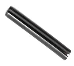
Spring Dowel Pin |
| |
 |
|
Outer Diameter
1mm to 100mm
Thickness
0.2mm to 15mm
Length
3mm to 250mm
|
|
| |
 |
Salient Features of |
|
Spring Dowel Pin : |
• Minimises the use of nuts and bolts.
• Stable locking can be attained.
• Longer service life.
• Ease of installation.
• Lower maintenance cost.
• Can be installed in sync with nuts and bolts.
|
Material of |
|
Spring Dowel Pin : |
Dowel Pins are manufactured out of Spring Steel 75 C 6 as per IS 2507 - 1975, heat-treated to 47 to 51 HRC. (Also see note)
|
Surface Finish of |
|
Spring Dowel Pin : |
Generally all Dowels Pins are thermally blackened. We also provide Zinc and Phosphate surface protection.
Quality Assurance:
All Dowel pins are thoroughly inspected for Dimensions like Outer Diameter, Inner Diameter, Length, Thickness, Longitudinal gap, Chamfer Length and Hardness according to IS:5988, DIN 1481 or as per party’s specification. Dowel are checked for resilience and recovery test in order to ensure better service life. |
| |
 |
| |
Table 1 : Preferred Lengths |
Length mm |
In steps of mm |
4 to 6 |
1 |
6 to 32 |
2 |
32 to 40 |
4 |
40 to 100 |
5 |
100 to 200 |
20 |
|
Table 2 : Tolerances on length |
Length mm |
Tolerance mm |
4 to 10 |
+ 0.5 |
12 to 50 |
+ 1.0 |
50 to 200 |
+ 1.5 |
|
|
| |
| |
| |
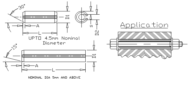
TABLE 3 : DIMENSIONS FOR SPRING DOWEL SLEEVES (LIGHT PATTERN) |
Catalogue No. |
Nominal Diameter Mm |
S |
A
|
Before Fitting |
For Bolt Size [IS:4218 (Part VI)- 1967*]6g |
Corres-ponding Washer (IS:2016- 1967**) |
Preferred Length Range (from Up to and including) L |
d1 |
Tol. on d1 |
d2
approx. |
P020L |
2 |
0.2 |
0.35 |
2.3 |
+ 0.1 |
1.9 |
- |
- |
4 - 30 |
P025L |
2.5 |
0.25 |
0.45 |
2.8 |
2.3 |
- |
- |
4 - 30 |
P030L |
3 |
0.3 |
0.5 |
3.3 |
+ 0.2 |
2.7 |
- |
- |
4 - 40 |
P035L |
3.5 |
0.35 |
0.6 |
3.8 |
3.1 |
- |
- |
4 - 40 |
P040L |
4 |
0.5 |
0.7 |
4.4 |
3.4 |
- |
- |
4 - 50 |
P045L |
4.5 |
0.5 |
0.8 |
4.8 |
3.8 |
M3 |
3.2 |
4 - 50 |
P050L |
5 |
0.5 |
1.6 |
5.4 |
4.4 |
- |
- |
5 - 80 |
P060L |
6 |
0.75 |
1.6 |
6.4 |
+ 0.3
|
4.9 |
M4 |
4.3 |
10-100 |
P070L |
7 |
0.75 |
1.6 |
7.5 |
6 |
M5 |
5.3 |
10-100 |
P080L |
8 |
0.75 |
2 |
8.5 |
7 |
M6 |
6.4 |
10-120 |
P100L |
10 |
1 |
2 |
10.5 |
8.5 |
- |
- |
10-160 |
P110L |
11 |
1 |
2 |
11.5 |
9.5 |
M8 |
8.4 |
10-160 |
P120L |
12 |
1 |
2 |
12.5 |
10.5 |
- |
- |
10-180 |
P130L |
13 |
1.25 |
2 |
13.5 |
11 |
M10 |
10.5 |
10-180 |
P140L |
14 |
1.5 |
2 |
14.5 |
11.5 |
- |
- |
10-180 |
P016L |
16 |
1.5 |
2 |
16.5 |
13.5 |
M12 |
13 |
10-200 |
P180L |
18 |
1.75 |
2 |
18.5 |
+ 0.4
|
15 |
M14 |
15 |
10-200 |
P200L |
20 |
2 |
2 |
20.5 |
16.5 |
- |
- |
10-200 |
P210L |
21 |
2 |
2 |
21.5 |
17.5 |
M16 |
17 |
14-200 |
P230L |
23 |
2 |
3 |
23.5 |
19.5 |
M18 |
19 |
14-200 |
P250L |
25 |
2 |
3 |
25.5 |
21.5 |
M20 |
21 |
14-200 |
P280L |
28 |
2.5 |
3 |
28.5 |
23.5 |
M22 |
23 |
14-200 |
P300L |
30 |
2.5 |
3 |
30.5 |
25.5 |
M24 |
25 |
14-200 |
P350L |
35 |
3.5 |
3 |
35.5 |
28.5 |
M27 |
28 |
20-200 |
P400L |
40 |
4 |
4 |
40.5 |
32.5 |
M30 |
31 |
20-200 |
P450L |
45 |
4 |
4 |
45.5 |
37.5 |
M36 |
37 |
20-200 |
P500L |
50 |
5 |
4 |
50.5 |
40.5 |
M39 |
40 |
20-200 |
* Limits of sizes for commercial nuts and bolts (Diameter range 1 to 39 mm)
** Specification for plain washers. |
| |
| |
TABLE 4 : DIMENSIONS FOR SPRING DOWEL SLEEVES (HEAVY PATTERN)
|
Catalogue
No.
|
Nominal
ø mm
|
S
|
A
|
Before Fitting |
For Bolt (Part VI) - 1967] 6g |
Corres- (IS:2016- 1967) |
Preferred and Including) L |
d1
|
Tol.
on d1 |
D2
approx. |
P010H |
1 |
0.2 |
0.15 |
1.2 |
+ 0.1 |
0.8 |
- |
- |
4-20 |
P015H |
1.5 |
0.3 |
0.25 |
1.7 |
1.1 |
- |
- |
4-20 |
P020H |
2 |
0.4 |
0.35 |
2.3 |
1.5 |
- |
- |
4-30 |
P025H |
2.5 |
0.5 |
0.45 |
2.8 |
1.8 |
- |
- |
4-30 |
P030H |
3 |
0.6 |
0.5 |
3.3 |
+ 0.2 |
2.1 |
- |
- |
4-40 |
P035H |
3.5 |
0.75 |
0.6 |
3.8 |
2.3 |
- |
- |
4-40 |
P040H |
4 |
0.8 |
0.7 |
4.4 |
2.8 |
- |
- |
4-50 |
P045H |
4.5 |
1 |
0.8 |
4.9 |
2.9 |
- |
- |
5-50 |
P050H |
5 |
1 |
1.6 |
5.4 |
3.4 |
- |
- |
5-80 |
P060H |
6 |
1.25 |
1.6 |
6.4 |
+ 0.3 |
3.9 |
M3 |
3.2 |
10-100 |
P080H |
8 |
1.5 |
2 |
8.5 |
5.5 |
M4 |
4.3 |
10-120 |
P100H |
10 |
2 |
2 |
10.5 |
6.5 |
M5 |
5.3 |
10-160 |
P120H |
12 |
2.5 |
2 |
12.5 |
7.5 |
M6 |
6.4 |
10-180 |
P130H |
13 |
2.5 |
2 |
13.5 |
8.5 |
- |
- |
10-180 |
P140H |
14 |
3 |
2 |
14.5 |
8.5 |
- |
- |
10-200 |
P160H |
16 |
3 |
2 |
16.5 |
10.5 |
M8 |
8.4 |
10-200 |
P180H |
18 |
3.5 |
2 |
18.5 |
+ 0.4 |
11.5 |
M10 |
10.5 |
10-200 |
P200H |
20 |
4 |
3 |
20.5 |
12.5 |
- |
- |
10-200 |
P210H |
21 |
4 |
3 |
21.5 |
13.5 |
M12 |
13 |
14-200 |
P250H |
25 |
5 |
3 |
25.5 |
15.5 |
M14 |
15 |
14-200 |
P280H |
28 |
5.5 |
3 |
28.5 |
17.5 |
M16 |
17 |
14-200 |
P300H |
30 |
6 |
3 |
30.5 |
18.5 |
- |
- |
14-200 |
P320H |
32 |
6 |
3 |
32.5 |
20.5 |
M18 |
19 |
20-200 |
P350H |
35 |
7 |
3 |
35.5 |
21.5 |
M20 |
21 |
20-200 |
P380H |
38 |
7.5 |
4 |
38.5 |
23.5 |
M22 |
23 |
20-200 |
P400H |
40 |
7.5 |
4 |
40.5 |
25.5 |
M24 |
25 |
20-200 |
P450H |
45 |
8.5 |
4 |
45.5 |
28.5 |
M27 |
28 |
20-200 |
P500H |
50 |
9.5 |
4 |
50.5 |
31.5 |
M30 |
31 |
20-200 |
|
| |
Ordering :
The basic format of ordering the Spring Dowel Pins is as follows
FOR LIGHT SERIES :
PAAALXXX
Where XXX is the length required. Light Spring dowel pin of 10 mm nominal diameter and length 40 mm to be ordered using catalogue no. Pl00L040, Where 040 is added instead of 40 mm.
FOR HEAVY SERIES :
PAAAHXXX
It is same as light series, but replace the letter L with letter H. Heavy Spring dowel pin of 10 mm nominal diameter and length 40 mm to be ordered using catalogue no. Pl00H040, Where 040 is added instead of 40 mm.
|
| |
|
| |
|
| |
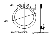
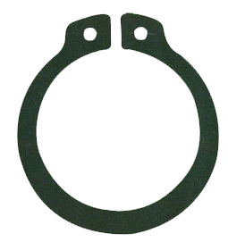
External Circlips |
| |
 |
|
Outer Diameter
6mm to 500mm
Thickness
0.4mm to 6mm
|
|
| |
|
Salient Features of |
|
External Circlips : |
| • |
They may be used to replace nuts, threaded sleeves, cotter pin, rivets, set collars, machined shoulders and many bulkier and more expensive fastening devices. |
| • |
As circlips are installed in pre-cut grooves, these pre-cut grooves can often be machined simultaneously with other production process; they eliminate threading, tapping, drilling, and other costly machining operations. |
| • |
Speed of assembly and disassembly further reduces manufacturing costs.
Space saving, compared to contemporary methods. |
| • |
Reduces assembly weight. |
| • |
Longer service life. |
|
Material of |
|
External Circlips : |
All the Circlips are manufactured from spring steel of grade such as 70C6 or 75C6 confirming to IS: 2507 - 1975 specification for cold rolled steel strips for springs (first revision).
|
Surface Finish of |
|
External Circlips : |
Unless the purchaser specifies any alternative finish, the circlip shall be chemically or thermally blackened.
Quality Assurance:
All circlips are thoroughly inspected for parameters like circlips thickness, internal diameter, conical deformation, spiral flatness, hardness and function like set and grip. |
| |
|
| |
Shaft |
CIRCLIP |
GROOVE DATA |
DIA |
s |
a |
b |
d3 |
Tol. On |
d4 |
d5 |
d2 |
Tol On |
M1 |
M2 |
N |
Axial |
d1 |
h11 |
Max |
Approx. |
|
d3 |
Expanded |
Min |
|
d2 |
H13 |
min |
Min |
Force Kgf |
8 |
0,8 |
3,2 |
1,5 |
7,4 |
+ 0,09 |
15,2 |
|
7,6 |
|
0,9 |
1,0 |
|
120 |
9 |
|
|
1,7 |
8,4 |
- 0,18 |
16,4 |
1,2 |
8,6 |
|
|
|
0,6 |
138 |
10 |
|
3,3 |
1,8 |
9,3 |
+0,15
-0.30 |
17,6 |
|
9,6 |
|
|
|
|
153 |
11 |
|
|
|
10,2 |
|
18,6 |
1,5 |
10,5 |
|
|
|
|
210 |
12 |
|
|
|
11 |
|
19,6 |
|
11,5 |
h11 |
|
|
0,75 |
230 |
13 |
1 |
3,4 |
2 |
11,9 |
|
20,8 |
|
12,4 |
|
1,1 |
1,2 |
|
300 |
14 |
|
3,5 |
2,1 |
12,9 |
+ 0,18 |
22,0 |
|
13,4 |
|
|
|
0,9 |
325 |
15 |
|
3,6 |
2,2 |
13,8 |
- 0,36 |
23,2 |
1,7 |
14,3 |
|
|
|
1,1 |
400 |
16 |
|
3,7 |
|
14,7 |
|
24,4 |
|
15,2 |
|
|
|
|
490 |
17 |
|
3,8 |
2,3 |
15,7 |
|
25,6 |
|
16,2 |
|
|
|
1,2 |
520 |
18 |
|
|
2,4 |
16,5 |
|
26,8 |
|
17,0 |
|
|
|
|
690 |
19 |
|
3,9 |
2,5 |
17,5 |
|
27,8 |
|
18,0 |
|
|
|
|
725 |
20 |
|
4,0 |
2,6 |
18,5 |
|
29,0 |
|
19,0 |
|
|
|
1,5 |
770 |
21 |
|
4,1 |
2,7 |
19,5 |
|
30,2 |
|
20,0 |
|
1,3 |
1,4 |
|
805 |
22 |
1,2 |
4,2 |
2,8 |
20,5 |
|
31,4 |
|
21,0 |
|
|
|
|
845 |
24 |
|
|
|
22,2 |
|
33,8 |
2,0 |
22,9 |
|
|
|
|
1010 |
25 |
|
4,4 |
3,0 |
23,2 |
+ 0,21 |
34,8 |
|
23,9 |
|
|
|
1,7 |
1060 |
26 |
|
4,5 |
3,1 |
24,2 |
- 0,42 |
36,0 |
|
24,9 |
|
|
|
|
1100 |
28 |
|
4,7 |
3,2 |
25,9 |
|
38,4 |
|
26,6 |
|
|
|
2,1 |
1500 |
29 |
|
4,8 |
3,4 |
26,9 |
|
39,6 |
|
27,6 |
|
|
|
|
1560 |
30 |
|
5,0 |
3,5 |
27,9 |
|
41,0 |
|
28,6 |
|
1,6 |
1,7 |
|
1620 |
32 |
1,5 |
5,2 |
3,6 |
29,6 |
|
43,4 |
|
30,3 |
|
|
|
|
2100 |
34 |
|
5,4 |
3,8 |
31,5 |
|
45,8 |
|
32,3 |
|
|
|
2,6 |
2220 |
35 |
|
5,6 |
3,9 |
32,2 |
+ 0,25 |
47,2 |
|
33,0 |
|
|
|
|
2670 |
36 |
|
|
4 |
33,2 |
- 0,50 |
48,2 |
|
34,0 |
|
|
|
3,0 |
2760 |
38 |
|
5,8 |
4,2 |
35,2 |
|
50,6 |
|
36,0 |
|
|
|
|
2910 |
40 |
|
6,0 |
4,4 |
36,5 |
|
53,0 |
|
37,5 |
|
1,85 |
2,0 |
|
3810 |
42 |
1,75 |
6,5 |
4,5 |
38,5 |
|
56,0 |
|
39,5 |
|
|
|
|
4000 |
45 |
|
6,7 |
4,7 |
41,5 |
+ 0,39 |
59,4 |
|
42,5 |
|
|
|
3,8 |
4300 |
48 |
|
|
5,0 |
44,5 |
- 0,78 |
62,8 |
2,5 |
45,5 |
|
|
|
|
4600 |
50 |
|
6,9 |
5,1 |
45,8 |
|
64,8 |
|
47,0 |
h12 |
|
|
|
5700 |
52 |
|
7,7 |
5,2 |
47,8 |
|
67,0 |
|
49,0 |
|
|
|
|
5950 |
55 |
|
7,2 |
5,4 |
50,8 |
|
70,4 |
|
52,0 |
|
|
|
|
6300 |
56 |
2,0 |
7,3 |
5,5 |
51,8 |
|
71,6 |
|
53,0 |
|
2,15 |
2,3 |
|
6400 |
58 |
|
|
5,6 |
53,8 |
|
73,6 |
|
55,0 |
|
|
|
|
6650 |
60 |
|
7,4 |
5,8 |
55,8 |
|
75,8 |
|
57,0 |
|
|
|
|
6900 |
62 |
|
7,5 |
6,0 |
57,8 |
|
78,0 |
|
59,0 |
|
|
|
|
6930 |
|
| |
Shaft |
CIRCLIP |
GROOVE DATA |
DIA |
s |
a |
b |
D3 |
Tol. On |
d4 |
D5 |
d2 |
Tol On |
M1 |
M2 |
n |
Axial |
d1 |
h11 |
Max |
Approx. |
|
d3 |
Expanded |
Min |
|
d2 |
H13 |
min |
min |
Force Kgf |
63 |
|
7,6 |
6,2 |
58,8 |
|
79,2 |
|
60,0 |
|
|
|
4,5 |
7020 |
65 |
|
7,8 |
6,3 |
60,8 |
+ 0,46 |
81,6 |
|
62,0 |
|
|
|
|
7500 |
68 |
|
8,0 |
6,5 |
63,5 |
- 0,92 |
85,0 |
|
65,0 |
|
|
|
|
7840 |
70 |
|
8,1 |
6,6 |
65,5 |
|
87,2 |
|
67,0 |
|
|
|
|
8050 |
72 |
|
8,2 |
6,8 |
67,5 |
|
89,4 |
|
69,0 |
|
2,65 |
2,8 |
|
8300 |
75 |
2,5 |
8,4 |
7,0 |
70,5 |
|
92,8 |
3,0 |
72,0 |
|
|
|
|
8600 |
78 |
|
8,6 |
7,3 |
73,5 |
|
96,2 |
|
75,0 |
|
|
|
|
9000 |
80 |
|
|
7,4 |
74,5 |
|
98,2 |
|
76,5 |
|
|
|
|
10700 |
82 |
|
8,7 |
7,6 |
76,5 |
|
101 |
|
78,5 |
|
|
|
|
11000 |
85 |
|
|
7,8 |
79,5 |
|
104 |
|
81,5 |
|
|
|
|
11400 |
88 |
|
8,8 |
8,0 |
82,5 |
|
107 |
|
84,5 |
|
|
|
|
11900 |
90 |
3,0 |
|
8,2 |
84,5 |
|
109 |
|
86,5 |
|
3,15 |
3,3 |
5,3 |
12100 |
95 |
|
9,4 |
8,6 |
89,5 |
|
115 |
|
91,5 |
|
|
|
|
12800 |
100 |
|
9,6 |
9 |
94,5 |
+ 0,54 |
121 |
3,5 |
96,5 |
|
|
|
|
13500 |
105 |
|
9,9 |
9,3 |
98,0 |
- 1,08 |
126 |
|
101 |
|
|
|
|
16200 |
110 |
|
10,1 |
9,6 |
103,0 |
|
132 |
|
106 |
|
|
|
|
17000 |
115 |
|
10,6 |
9,8 |
108,0 |
|
138 |
|
111 |
|
|
|
|
17800 |
120 |
|
11,0 |
10,2 |
113,0 |
|
143 |
|
116 |
|
|
|
|
18500 |
125 |
|
11,4 |
10,4 |
118,0 |
|
149 |
|
121 |
|
|
|
6 |
19300 |
130 |
|
11,6 |
10,7 |
123,0 |
|
155 |
|
126 |
|
|
|
|
20100 |
135 |
|
11,8 |
11 |
128,0 |
|
160 |
|
131 |
|
|
|
|
20900 |
140 |
|
12,0 |
11,2 |
133,0 |
|
165 |
|
136 |
|
|
|
|
21700 |
145 |
|
12,2 |
11,5 |
138,0 |
|
171 |
|
141 |
|
|
|
|
22500 |
150 |
|
13,0 |
11,8 |
142,0 |
|
177 |
|
145 |
|
4,15 |
4,3 |
|
28900 |
155 |
4,0 |
|
12,0 |
146,0 |
+ 0,63 |
182 |
|
150 |
|
|
|
|
30000 |
160 |
|
13,3 |
12,2 |
151,0 |
- 1,26 |
188 |
|
155 |
|
|
|
|
31000 |
165 |
|
13,5 |
12,5 |
155,5 |
|
193 |
|
160 |
|
|
|
|
32000 |
170 |
|
|
12,9 |
160,5 |
|
197 |
|
165 |
|
|
|
|
32900 |
175 |
|
|
Max |
165,5 |
|
202 |
4,0 |
170 |
|
|
|
|
33800 |
180 |
|
|
13,5 |
170,5 |
|
208 |
|
175 |
h13 |
|
|
|
34500 |
185 |
|
|
Max |
175,5 |
|
213 |
|
180 |
|
|
|
7,5 |
33800 |
190 |
|
|
|
180,5 |
|
219 |
|
185 |
|
|
|
|
33500 |
195 |
|
|
|
185,5 |
|
224 |
|
190 |
|
|
|
|
32700 |
200 |
|
|
|
190,5 |
|
229 |
|
195 |
|
|
|
|
31900 |
210 |
|
|
14,0 |
198 |
|
239 |
|
204 |
|
|
|
|
48800 |
220 |
|
|
Max |
208 |
+ 0,72 |
249 |
|
214 |
|
|
|
|
51200 |
230 |
|
|
|
218 |
- 1,44 |
259 |
|
224 |
|
|
|
9,0 |
53500 |
240 |
|
|
|
228 |
|
269 |
|
234 |
|
|
|
|
52900 |
250 |
5,0 |
|
|
238 |
|
279 |
|
244 |
|
5,2 |
5,3 |
|
50300 |
260 |
|
|
|
245 |
|
293 |
|
252 |
|
|
|
|
54400 |
270 |
|
|
|
255 |
|
303 |
|
262 |
|
|
|
|
52500 |
280 |
|
|
16,0 |
265 |
+ 0,81 |
313 |
5,0 |
272 |
|
|
|
12,0 |
50800 |
290 |
|
|
Max |
275 |
- 1,62 |
323 |
|
282 |
|
|
|
|
49100 |
300 |
|
|
|
285 |
|
333 |
|
292 |
|
|
|
|
47300 |
|
|
| |
|
| |
|
| |
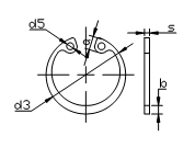
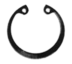
Internal Circlips |
| |
 |
|
Outer Diameter
8mm to 500mm
Thickness
0.4mm to 6mm
|
|
| |
|
Salient Features of |
|
Internal Circlips : |
| • |
As circlips are installed in pre-cut grooves, these pre-cut grooves can often be machined simultaneously with other production process; they eliminate threading, tapping, drilling, and other costly machining operations. |
| • |
Speed of assembly and disassembly further reduces manufacturing costs. |
| • |
Space saving, compared to contemporary methods. |
| • |
Reduces assembly weight. |
| • |
Longer service life. |
|
Material of |
|
Internal Circlips : |
All the Circlips are manufactured from spring steel of grade such as 70C6 or 75C6 confirming to IS: 2507 - 1975 specification for cold rolled steel strips for springs (first revision).
|
Surface Finish of |
|
Internal Circlips : |
Unless the purchaser specifies any alternative finish, the circlips shall be chemically or thermally blackened.
Quality Assurance:
All circlips are thoroughly inspected for parameters like circlips thickness, internal diameter, conical deformation, spiral flatness, hardness and function like set and grip. |
| |
|
| |
BORE
&
d1 |
CIRCLIP |
BORE GROOVE |
S
H11 |
a
Max |
b
Approx |
d3 |
Tol. On
d3 |
d4
Compressed |
d5
min. |
d2 |
Tol. on
d2 |
m1
H13 |
m2
min. |
n
min. |
Axial
Force
Kgf |
8 |
0.8 |
2.4 |
1.1 |
8.7 |
|
2.8 |
1 |
8.4 |
|
|
|
|
128 |
9 |
2.5 |
1.3 |
9.8 |
|
3.5 |
9.4 |
|
0.9 |
1 |
0.6 |
144 |
10 |
1 |
3.2 |
1.4 |
10.8 |
|
3.1 |
1.2 |
10.4 |
|
|
|
|
160 |
11 |
3.3 |
1.5 |
11.8 |
|
3.9 |
11.4 |
|
|
|
|
176 |
12 |
3.4 |
1.7 |
13 |
+ 0.36 |
4.7 |
1.5 |
12.5 |
|
|
|
0.75 |
240 |
13 |
3.6 |
1.8 |
14.1 |
- 0.18 |
5.3 |
13.6 |
H11 |
|
|
0.9 |
314 |
14 |
|
1.9 |
15.1 |
|
6 |
1.7 |
14.6 |
|
|
|
|
336 |
15 |
3.7 |
|
16.2 |
|
7 |
15.7 |
|
1.1 |
1.2 |
1.1 |
422 |
16 |
3.8 |
2 |
17.3 |
|
7.7 |
16.8 |
|
|
|
1.2 |
515 |
17 |
3.9 |
2.1 |
18.3 |
|
8.4 |
17.8 |
|
|
|
|
547 |
18 |
|
|
19.5 |
|
8.9 |
2 |
19 |
|
|
|
|
725 |
19 |
4.1 |
2.2 |
20.5 |
|
9.8 |
20 |
|
|
|
|
764 |
20 |
|
2.3 |
21.5 |
|
10.6 |
21 |
|
|
|
1.5 |
780 |
21 |
4.2 |
2.4 |
22.5 |
+ 0.42 |
11.6 |
22 |
|
|
|
|
810 |
22 |
|
2.5 |
23.5 |
- 0.21 |
12.6 |
23 |
H12 |
|
|
|
835 |
24 |
1.2 |
4.4 |
2.6 |
25.9 |
|
14.2 |
25.2 |
|
|
|
|
1160 |
25 |
4.5 |
2.7 |
26.9 |
|
15 |
26.2 |
|
|
|
1.8 |
1200 |
26 |
4.7 |
2.8 |
27.9 |
|
15.6 |
27.2 |
|
1.3 |
1.4 |
|
1250 |
28 |
4.8 |
2.9 |
30.1 |
|
17.4 |
29.4 |
|
|
|
2.1 |
1330 |
30 |
4.8 |
3 |
32.1 |
|
19.4 |
31.4 |
|
|
|
|
1370 |
31 |
5.2 |
3.2 |
33.4 |
|
19.6 |
2.5
|
32.7 |
|
|
|
|
1380 |
32 |
|
3.2 |
34.4 |
|
20.2 |
33.7 |
|
|
|
2.6 |
1390 |
34 |
1.5 |
|
3.3 |
36.5 |
+ 0.50 |
22.2 |
35.7 |
|
|
|
|
2320 |
35 |
5.4 |
3.4 |
37.8 |
- 0.25 |
23.2 |
37 |
|
|
|
|
2690 |
36 |
|
3.5 |
38.8 |
|
24.2 |
38 |
|
1.6 |
1.7 |
3 |
2640 |
37 |
5.5 |
3.6 |
39.8 |
|
25 |
39 |
|
|
|
|
2716 |
38 |
|
3.7 |
40.8 |
|
26 |
40 |
|
|
|
|
2820 |
40 |
1.75 |
5.8 |
3.9 |
43.5 |
+ 0.78
- 0.39 |
27.4 |
42.5 |
|
|
|
|
4050 |
42 |
5.9 |
4.1 |
45.5 |
29.2 |
44.5 |
|
|
|
|
4250 |
45 |
6.2 |
4.3 |
48.5 |
31.6 |
47.5 |
|
1.85 |
2 |
3.8 |
4310 |
47 |
|
4.4 |
50.5 |
+ 0.92
- 0.46 |
33.2 |
49.5 |
|
|
|
|
4350 |
48 |
6.4 |
4.5 |
51.5 |
34.6 |
50.5 |
|
|
|
|
4320 |
51 |
2 |
6.5 |
4.6 |
54.2 |
36 |
53 |
|
|
|
|
6070 |
52 |
6.7 |
4.7 |
56.2 |
37.6 |
55 |
|
|
|
|
6025 |
55 |
|
5 |
59.2 |
40.4 |
58 |
|
|
|
|
6350 |
56 |
6.8 |
5.1 |
60.2 |
41.4 |
59 |
|
2.15 |
2.3 |
|
6075 |
58 |
6.9 |
5.2 |
62.2 |
43.2 |
61 |
|
|
|
|
6150 |
60 |
2 |
|
5.4 |
64.2 |
44.4 |
63 |
H12 |
|
|
|
6210 |
62 |
7.3 |
5.5 |
66.2 |
46.4 |
65 |
|
|
|
4.5 |
6170 |
63 |
|
5.6 |
67.2 |
47.4 |
66 |
|
|
|
|
6160 |
65 |
|
7.6 |
5.8 |
69.2 |
48.8 |
3 |
68 |
|
|
|
|
7820 |
68 |
|
|
6.1 |
72.5 |
51.4 |
71 |
|
|
|
|
8170 |
70 |
|
|
6.2 |
74.5 |
53.4 |
73 |
|
|
|
|
8420 |
72 |
2.5 |
7.8 |
6.4 |
76.5 |
55.4 |
75 |
|
2.65 |
2.8 |
|
8650 |
75 |
|
|
6.6 |
79.5 |
58.4 |
78 |
|
|
|
|
9000 |
BORE
&
d1 |
CIRCLIP |
GROOVE DATA |
S
H11 |
a
Max |
b
Approx |
d3 |
Tol.on
d3 |
d4
Compressed |
d5
Min. |
d2 |
Tol. On
d2 |
m1
H13 |
m2
min |
n
min |
Axial
Force
Kgf |
78 |
|
|
6.8 |
82.5 |
+ 1.08
- 0.54 |
60 |
3 |
81 |
|
|
|
|
9350 |
80 |
|
8.5 |
7 |
85.5 |
62 |
83.5 |
|
|
|
|
11200 |
82 |
|
|
|
87.5 |
64 |
85.5 |
|
|
|
|
11500 |
85 |
|
|
7.2 |
90.5 |
66.8 |
|
88.5 |
|
|
|
|
11900 |
88 |
|
8.6 |
7.4 |
93.5 |
69.8 |
|
91.5 |
|
|
|
|
12300 |
90 |
|
|
7.6 |
95.5 |
71.8 |
|
93.5 |
|
|
|
|
12600 |
92 |
3 |
8.7 |
7.8 |
97.5 |
73.6 |
|
195.5 |
|
3.15 |
3.3 |
5.3 |
12900 |
95 |
|
8.8 |
8.1 |
100.5 |
76.4 |
|
198.5 |
|
|
|
|
13300 |
98 |
|
|
8.3 |
103.5 |
79 |
|
101.5 |
|
|
|
|
13700 |
100 |
|
9 |
8.4 |
105.5 |
81 |
3.5 |
103.5 |
|
|
|
|
14000 |
102 |
|
|
8.5 |
108 |
82.6 |
|
106 |
H13 |
|
|
|
16300 |
105 |
|
9.2 |
8.7 |
112 |
85.6 |
|
109 |
|
|
|
16800 |
108 |
|
9.5 |
8.9 |
115 |
88 |
|
112 |
|
|
|
17300 |
110 |
|
10.4 |
9 |
117 |
88.2 |
|
114 |
|
|
|
17600 |
112 |
|
|
9.1 |
119 |
90 |
|
116 |
|
|
|
17900 |
115 |
|
10.5 |
9.3 |
122 |
+ 1.26
- 0.63 |
93 |
|
119 |
|
|
6 |
18400 |
120 |
|
|
9.7 |
127 |
97 |
|
124 |
|
|
|
19200 |
125 |
|
11 |
10 |
132 |
102 |
4 |
129 |
|
|
|
19900 |
130 |
|
|
10.2 |
137 |
107 |
134 |
|
|
|
20700 |
135 |
|
11.2 |
10.5 |
142 |
112 |
139 |
|
|
|
21500 |
140 |
|
10.7 |
147 |
117 |
144 |
|
|
|
22300 |
145 |
|
11.4 |
10.9 |
152 |
122 |
149 |
|
|
|
23100 |
150 |
|
12 |
11.2 |
158 |
125 |
155 |
|
|
|
30000 |
155 |
4 |
11.4 |
164 |
130 |
160 |
4.15 |
4.3 |
|
30900 |
160 |
|
|
11.6 |
169 |
133 |
165 |
|
|
|
31900 |
170 |
|
|
12.2 |
179.5 |
|
145 |
175 |
|
|
|
33900 |
175 |
|
12.7 |
184.5 |
+ 1.44
- 0.72 |
149 |
180 |
|
|
7.5 |
34800 |
180 |
|
13.2 |
189.5 |
153 |
185 |
|
|
|
34500 |
185 |
|
13.7 |
194.5 |
157 |
190 |
|
|
|
34930 |
190 |
|
13.8 |
199.5 |
162 |
195 |
|
|
|
34000 |
195 |
|
13.8 |
204.5 |
167 |
200 |
|
|
|
33000 |
200 |
|
14
Max |
209.5 |
171 |
205 |
|
|
|
32500 |
210 |
|
222 |
181 |
216 |
|
|
|
|
50000 |
220 |
|
232 |
191 |
226 |
|
|
|
|
52200 |
230 |
|
242 |
201 |
236 |
|
|
|
9 |
54900 |
240 |
|
252 |
+ 1.62
- 0.81 |
211 |
246 |
|
|
|
|
52500 |
250 |
5 |
262 |
221 |
256 |
|
5.15 |
5.3 |
|
50500 |
260 |
|
16
Max |
275 |
227 |
5 |
268 |
|
|
|
|
54000 |
270 |
|
285 |
237 |
278 |
|
|
|
|
51800 |
280 |
|
295 |
247 |
288 |
|
|
|
12 |
50000 |
290 |
|
305 |
257 |
298 |
|
|
|
|
48200 |
300 |
|
315 |
267 |
308 |
|
|
|
|
46500 |
|
| |
|
|
| |
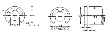
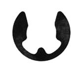
E-Type Circlips |
| |
 |
|
Outer Diameter
1.5mm to 24mm
Thickness
0.4mm to 2mm
|
|
| |
|
Material and Hardness of |
|
E-Type Circlips : |
All the Circlips are manufactured from spring steel of grade such as 70C6 or 75C6 confirming to IS : 2507 - 1975 specification for cold rolled steel strips for springs (first revision).
Hardness of Circlip is between 460 to 580 HV (Corresponding to 46 to 54 HRC)
|
Surface Finish of |
|
E-Type Circlips : |
Unless the purchaser specifies any alternative finish, the circlip shall be chemically or thermally blackened.
|
| |
|
| |
Nominal |
Circlip |
Shaft Groove |
size |
d4 |
A |
S |
Tol |
D3 |
d2 |
m |
Tol. on |
d1 |
Expanded |
H10 |
|
on s |
From |
To |
h11 |
|
m |
0.8 |
2 |
0.58 |
0.20 |
|
1 |
1.4 |
0.8 |
0.24 |
|
1.2 |
3 |
1.01 |
0.30 |
|
1.4 |
2 |
1.2 |
0.34 |
± 0.02 |
1.5 |
4 |
1.28 |
0.40 |
|
2 |
2.5 |
1.5 |
0.44 |
|
1.9 |
4.5 |
1.61 |
0.50 |
|
2.5 |
3 |
1.9 |
0.54 |
|
2.3 |
6 |
1.94 |
0.60 |
|
3 |
4 |
2.3 |
0.64 |
|
3.2 |
7 |
2.70 |
0.60 |
± 0.02 |
4 |
5 |
3.2 |
0.64 |
|
4.0 |
9 |
3.34 |
0.70 |
|
5 |
7 |
4 |
0.74 |
± 0.03 |
5.0 |
11 |
4.11 |
0.70 |
|
6 |
8 |
5 |
0.74 |
|
6.0 |
12 |
5.26 |
0.70 |
|
7 |
9 |
6 |
0.74 |
|
7.0 |
14 |
5.84 |
0.90 |
|
8 |
11 |
7 |
0.94 |
|
8.0 |
16 |
6.52 |
1.00 |
|
9 |
12 |
8 |
1.05 |
|
9.0 |
18.5 |
7.63 |
1.10 |
|
10 |
14 |
9 |
1.15 |
|
10 |
20 |
8.32 |
1.20 |
|
11 |
15 |
10 |
1.25 |
|
12 |
23 |
10.45 |
1.30 |
± 0.03 |
13 |
18 |
12 |
1.35 |
± 0.06 |
15 |
29 |
12.61 |
1.50 |
|
16 |
24 |
15 |
1.55 |
|
19 |
37 |
15.92 |
1.75 |
|
20 |
31 |
19 |
1.80 |
|
24 |
44 |
21.88 |
2.00 |
|
25 |
38 |
24 |
2.05 |
|
|
| |
| |
|
| |
|
| |
Enquiry Form |
| |
|
| |
*
Indicates Compulsory Fields
|
|
|
|
| |
|
|